I think that there are a lot of troubles due to the liquid crystal cracking because Nintendo Switch can carry it.
Because it is a touch panel cracking, liquid crystal panel and two layers, this decomposition method can cope with both failures.
The process of changing the liquid crystal is long to the state of almost all balassi, and I think that it takes about one to two hours if it is disassembled for the first time, so it is better to disassemble and repair it when there is time.
[Switch LCD replacement and repair method 1]
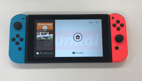
We will continue to disassemble The Switch, so let's remove the Joycon that is attached to both sides first!
Also, be sure to remove the disassembly with the power down.
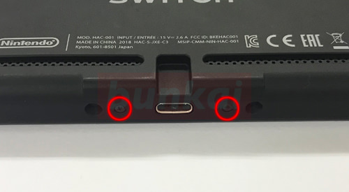
[Switch LCD replacement and repair method 2]
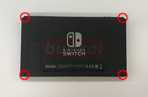
All disassemblies are done from the back, but the screw in the red circle part is removed with the screwdriver first.
To remove the LCD panel, it is necessary to disassemble it to almost the state of the whole barassi.
So, please look over the process to see if you can repair it yourself before disassembling.
Because it is thought that it becomes a rather high repair fee if it fails in the process in the middle by any chance.
[Switch LCD replacement and repair method 3]
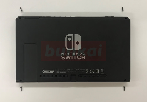
I was able to remove the screw, but please keep it so as not to lose it so as not to remove the screw further in the future.
Because there are various kinds of shape and length of the screw, please disassemble it in a little large space.
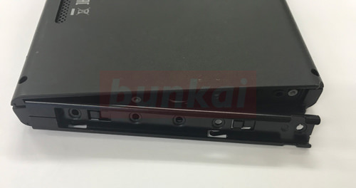
[Switch LCD replacement and repair method 4]
This is the dock connector side, but there are two screws, so I will remove it.
[Switch LCD replacement and repair method 5]
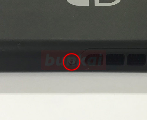
This is the upper side, but the screw is removed.
[Switch LCD replacement and repair method 6]
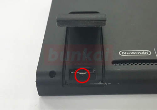
There is a screw in the part where micro SD is inserted, but it is a place that tends to forget unexpectedly.
Let's open the lid by hand and remove the screw with the screwdriver.
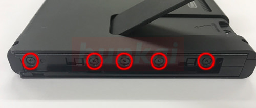
[Switch LCD replacement and repair method 7]
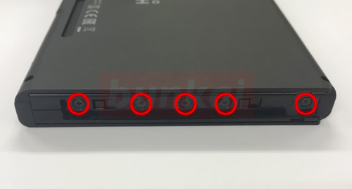
Here is the part to insert the Joycon, but there are five screws.
Remove all screws with a screwdriver.
[Switch LCD replacement and repair method 8]
If you can remove all the screws, the parts will come off slightly for the image, but it will not come off completely, so it will be okay for the time being.
[Switch LCD replacement and repair method 9]
It is the Joycon part on the other side.
Because it becomes the same method as decomposition, let's remove the screw in the same manner as before.
[Switch LCD replacement and repair method 10]
The parts come off slightly in the same way, but for the time being, this is also okay as it is.
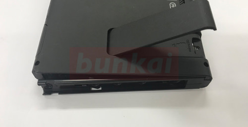
[Switch LCD replacement and repair method 11]
It is possible to lift the back cover as shown in the image when all screws up to the above process can be removed.
I try to cause it gradually from the dock connector side (charge part), but if there is a hard part on the way, please check again because there is a possibility of forgetting to remove the screw.
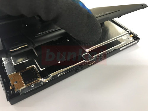
[Switch LCD replacement and repair method 12]
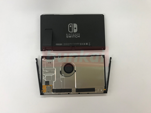
It was possible to remove the back cover from the main body.
Decomposition gradually becomes complicated from here, so let's perform the decomposition while checking the structure.
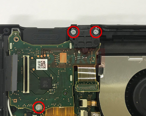
[Switch LCD replacement and repair method 13]
The inner motherboard is protected by the iron shield.
First of all, it becomes from the process of removing this shield, but it is fixed to the main body with several screws.
Let's remove the screw of the red circle part.
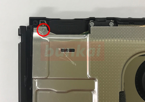
[Switch LCD replacement and repair method 14]
This is the bottom right.
Let's remove the screw as before.
[Switch LCD replacement and repair method 15]
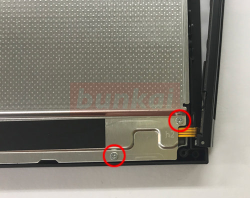
This part is a micro SD outlet, but be careful not to damage the base when removing the screw.
[Switch LCD replacement and repair method 16]
This is the upper left.
Let's remove the screw in the same way.
[Switch LCD replacement and repair method 17]
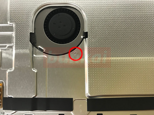
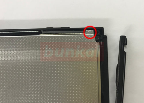
There is a screw in the FAN in the middle, so don't forget to remove it.
[Switch LCD replacement and repair method 18]
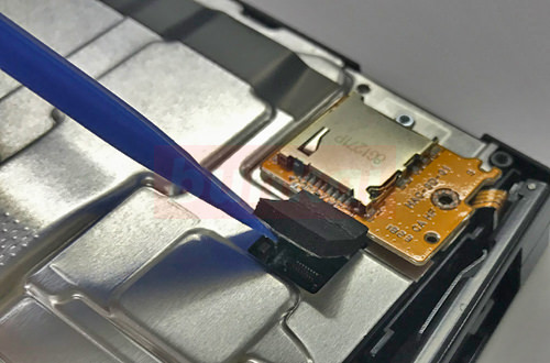
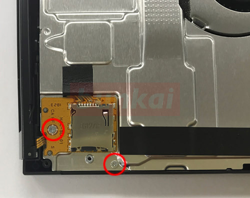
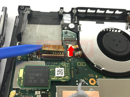
The base of the previous micro SD is connected to the motherboard by a connector.
It is possible to remove the connector by inserting the tool from the bottom as shown in the image and lifting it upward.
[Switch LCD replacement and repair method 19]
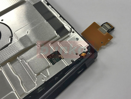
It is possible to remove it easily if you wake up the base of micro SD as it is.
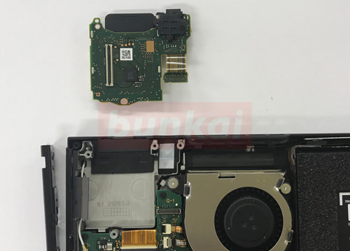
[Switch LCD replacement and repair method 20]
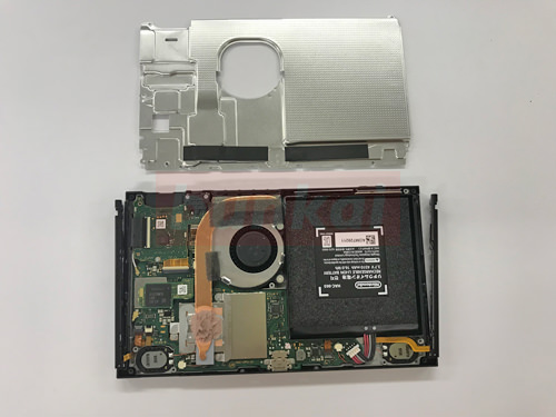
If you can remove all the base and screws of the micro SD, you can remove the silver plate.
We haven't done half of the decomposition so far, so be especially careful about the decomposition from here on.
[Switch LCD replacement and repair method 21]
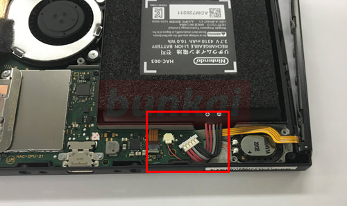
Be sure to remove the battery connector before removing the LCD.
If you proceed with the disassembly without doing this, there is a possibility of short-circuiting, and it may lead to serious failure, such as the power does not turn on, so be careful.
I think that you can check the battery as soon as you can remove the silver plate, but the part enclosed in the red frame is where the battery connector is connected to the motherboard.
[Switch LCD replacement and repair method 22]
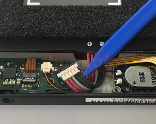
It is possible to remove the connector by inserting the plastic tool down as shown in the image and lifting it up.
[Switch LCD replacement and repair method 23]
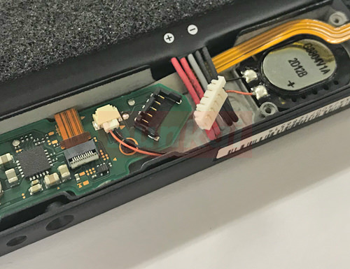
Now i was able to cut off the electricity from the Switch body.
From here, we enter into the decomposition of the liquid crystal side.
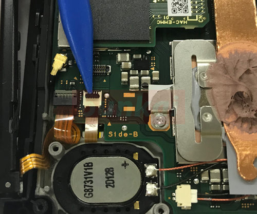
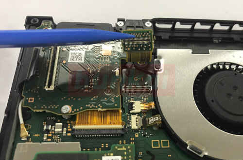
[Switch LCD replacement and repair method 24]
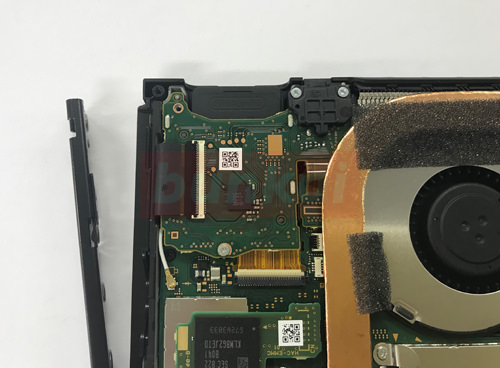
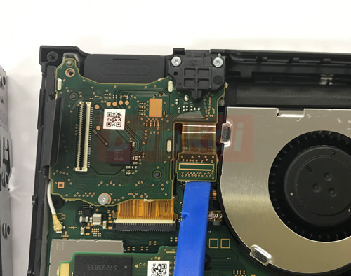
The cable on the touch panel and the cable on the LCD panel are connected to the green base (motherboard), but the cable is removed first.
[Switch LCD replacement and repair method 25]
Remove the cable from the part of the tool, but do not pull the cable out as it is.
There is a black plastic nail at the tip of the tool, so let the nails be raised before the cable is removed.
Black nails can be raised up to 90 degrees, but please be careful because if you bend it more than 90 degrees, the nail may break.
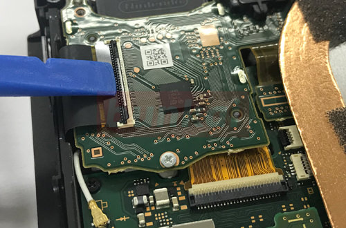
[Switch LCD replacement and repair method 26]
It is possible to remove the cable as in the image when it is possible to wake the nail.
[Switch LCD replacement and repair method 27]
There is a similar cable in the immediate vicinity of the previous cable, so let's remove it in the same way.
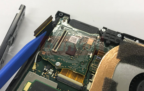
[Switch LCD replacement and repair method 28]
It becomes the position of the image when it comes down as it is, but the size of the cable is different from the previous one, but let's remove it because the way of removing it becomes the same.
[Switch LCD replacement and repair method 29]
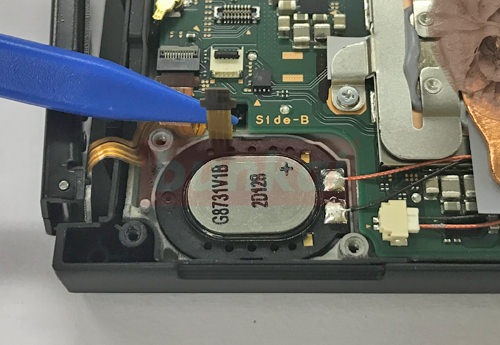
The backlight cable could be removed from the motherboard.
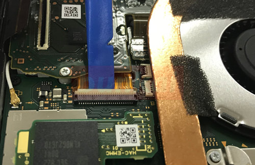
[Switch LCD replacement and repair method 30]
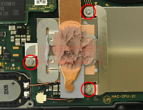
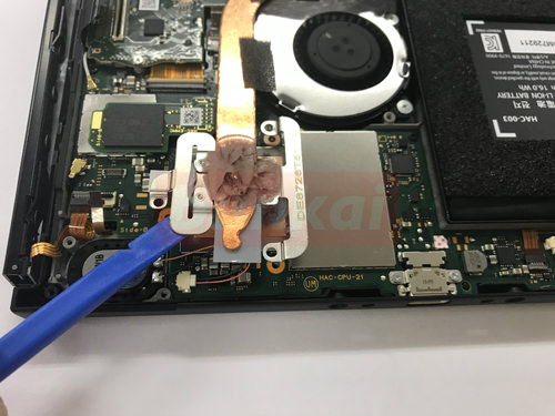
Next, remove the heat sink covering the FAN, but let's remove it because there are three screws in the part where grease is applied.
[Switch LCD replacement and repair method 31]
This is the FAN side, but the heat sink and FAN are stopped by tape and screws.
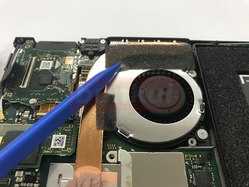
[Switch LCD replacement and repair method 32]
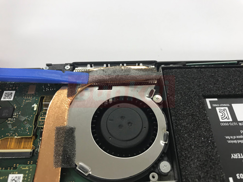
Just turn the tape like the image.
There is a tape on the side and vertically, so let's turn each one.
[Switch LCD replacement and repair method 33]
It is possible to remove the heat sink by lifting it up because the tool was used.
[Switch LCD replacement and repair method 34]
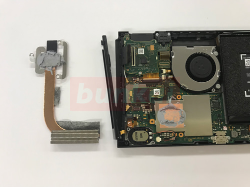
The heatsink could be removed.
[Switch LCD replacement and repair method 35]
The lower part of the heat sink is the image part, but the connector is connected, so it is possible to remove it if you try to lift the tool down into the plug.
This part is the connector of the earphone.
[Switch LCD replacement and repair method 36]
I was able to remove the connector as shown in the image.
[Switch LCD replacement and repair method 37]
I will decompose the same part (base) as it is, but this part is also where the cassette, earphones are connected, the cassette is not loaded, If there seems to be no sound coming out of the earphone, it may improve if you replace this base.
Remove all the red-circle screws.
[Switch LCD replacement and repair method 38]
I was able to remove the base of the earphone jack.
[Switch LCD replacement and repair method 39]
The ribbon cable under the base can be removed by sliding in the direction of the arrow.
[Switch LCD replacement and repair method 40]
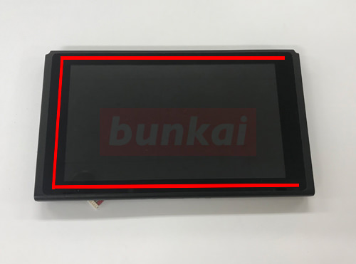
From here on, we will disassemble the touch panel side, but the touch panel is attached to the frame of the Switch body with a powerful double-sided tape.
The tape is attached to the inside of the red line, but it is difficult to peel it off as it is, so it is peeled off using a tool.
I don't draw a red line on the right side, but I'll explain this part later.
[Switch LCD replacement and repair method 41]
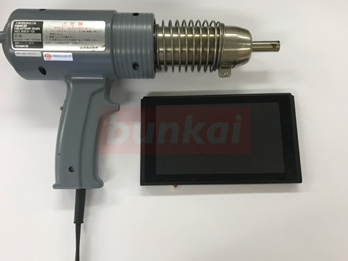
A tool is a heat gun.
I think that there is a person who knows the heat gun for the first time, but the point is a powerful thing of the dryer.
It is an image that heats the red line part of Step 40 and peels off while softening double-sided tape.
Heat gun can be substituted to some extent even with a home dryer, but the heat gun is better as work efficiency because the heat gun is stronger.
[Switch LCD replacement and repair method 42]
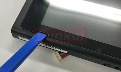
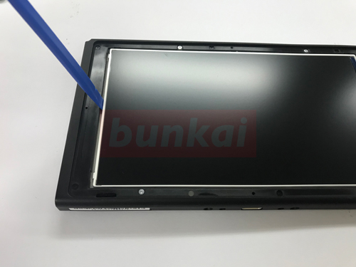
The image part is where there is a recess from the original, but please insert the tool from this position.
After applying the heat, insert the tool and peel it off so that you can receive the touch panel a little at a time.
If you change the liquid crystal inside the LCD rather than a problem with the touch panel, please be careful not to break the liquid crystal because it reuses the touch panel.
[Switch LCD replacement and repair method 43]
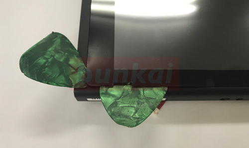
You can prevent re-adhesion by inserting a tool (pick image) into the part where the touch panel floats even a little.
[Switch LCD replacement and repair method 44]
The current image has been working to peel off by applying heat to the "reverse co-shaped" (top, bottom, left), but please see the following image why you are leaving only the right side.
[Switch LCD replacement and repair method 45]
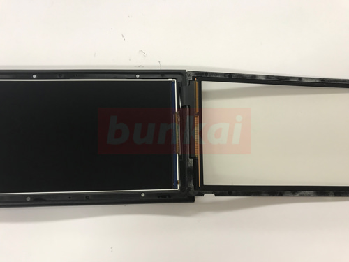
The touch panel is open, but only the right part is connected cable.
If you turn off this cable when reusing the touch panel, you need to be careful enough to prevent the touch from working.
[Switch LCD replacement and repair method 46]
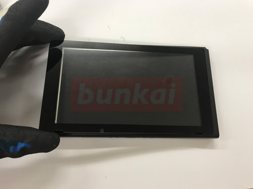
If you pull the touch panel while paying attention to the disconnection of the cable, you can remove it as shown in the image.
The display of the LCD panel is normal, and in the case of cracks, cracks, and cracks in the touch panel, it will be terminated by decomposition so far.
Replace the newly prepared touch panel and reassemble it with the original procedure.
If there is a display defect or leakage on the monitor, it is necessary to disassemble it in the future.
[Switch LCD replacement and repair method 47]
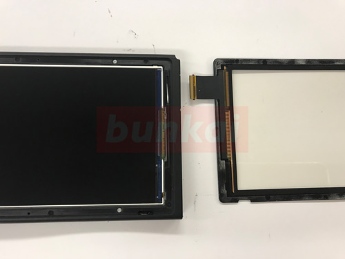
If you can remove the touch panel l, it is easy to remove the LCD panel inside.
Insert a thin tip tool into The Yokogawa as shown in the image.
[Switch LCD replacement and repair method 48]
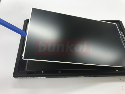
Just wake it up from the left side to the right side.
[Switch LCD replacement and repair method 49]
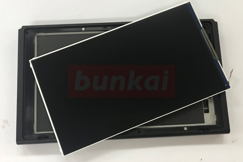
The LCD panel could be removed, but if there is a leak or display defect in the LCD panel, it is necessary to disassemble up to this point.